
How Does Servo Positioning Improve Rigid Box Making Accuracy?
Servo positioning improves rigid box making accuracy by controlling the movement used to place greyboard at a set location. Combined with suitable detection and control systems, it helps keep board placement consistent. Final accuracy also depends on mechanical stability, material dimensions and processing conditions.
Detection, Movement and Results
Sensors detect a reference. The controller calculates the required action. The servo-driven mechanism moves the material. Measurements of the processed case show the actual result.
What Is Servo Positioning?
Servo positioning uses a motor, drive and feedback system to control movement toward a commanded position. In rigid case making, that movement may drive a conveyor, board feeder or placement mechanism, depending on the machine.
A typical servo system uses encoder feedback to monitor motor movement and help correct the difference between commanded and measured motion.
However, motor feedback does not automatically measure the board itself. A motor can reach its target while the board shifts slightly because of slipping, gripping variation or mechanical play. Direct material-position feedback requires additional detection where provided.
How Does a Servo System Control Board Placement?
The controller commands the positioning mechanism to move the board or covering sheet to the required location, using the machine’s configured references and movement settings.
- Set the layout. The operator enters or adjusts the case dimensions, board positions and joint gaps supported by the machine.
- Establish the reference. Sensors, cameras or mechanical locating features provide the information required by that configuration.
- Control the movement. The servo system manages travel, speed and acceleration to bring the mechanism to its commanded position.
- Place and transfer the workpiece. The boards contact the glued covering sheet, and the case continues to folding.
The benefit comes from repeating controlled movements and coordinating them with material arrival. Whether the machine corrects each sheet individually, and which deviations it can correct, depends on its detection and control architecture.
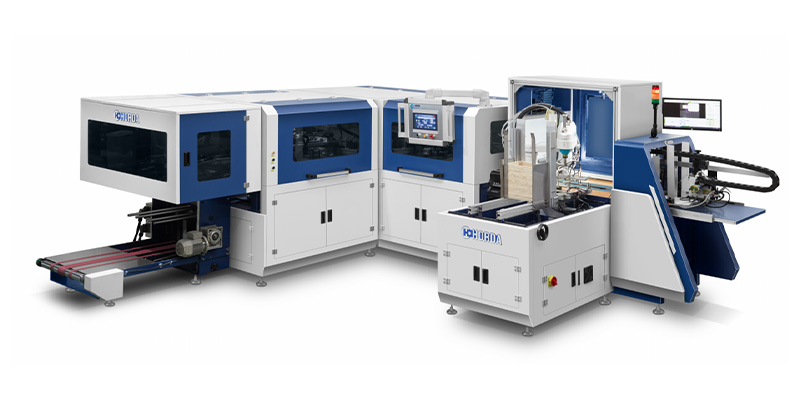
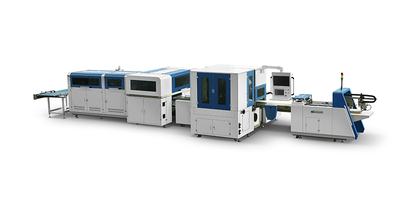
For example, HORDA’s ZFM-700H/1000H description combines servo correction, secondary conveyor positioning and photoelectric detection. When reviewing a rigid box making machine, check how these functions work together rather than judging the servo system alone.
What Is the Role of Photoelectric Detection?
Photoelectric detection supplies a signal about a material reference, such as a sheet reaching a sensing point. The controller can use that signal to coordinate or adjust movement where the machine supports it.
Photoelectric Sensor
Detects a suitable optical change, such as material presence, an edge or a compatible mark.
CCD Vision System
Uses images to locate features supported by its lighting, optics and recognition software.
Servo Mechanism
Executes the commanded movement. It needs suitable reference information to position material relative to the intended target.
A machine may combine servo motion with photoelectric detection or camera guidance. These terms describe different functions and should not be treated as interchangeable positioning technologies.
How Are Front, Back and Spine Boards Aligned?
The machine places the boards according to a defined layout, controlling their relationship to the cover paper and to one another. The feeding and positioning arrangement varies by model.
For a typical three-piece hardcover case, the front and back boards sit on either side of the spine board. The gaps between them form the flexible joints.
- Panel position: Keeps each board in its intended location on the covering sheet.
- Board spacing: Establishes the specified joints between the spine and outer panels.
- Squareness: Helps keep panel edges parallel and prevents a skewed layout.
- Cover registration: Aligns the layout to the selected paper edge, mark or artwork reference.
Servo control can make placement more repeatable, but it cannot correct an incorrectly cut board. Inconsistent dimensions can still produce uneven margins or joints even when the positioning mechanism repeats its movement accurately.
Servo Positioning vs. Manual Adjustment
Servo positioning repeats controlled movements during production, while manual adjustment establishes or changes the machine’s setup. Many machines use both.
Operators may still adjust guides, loading positions, gripping components or folding settings. Servo control then helps execute the configured production movements consistently.
- During production: Controlled travel and timing can reduce variation associated with repeated manual placement.
- During changeover: Supported electronic settings may reduce some adjustments, although mechanical changes can remain necessary.
- During quality checks: Operators confirm that the settings produce acceptable board spacing, margins and folded cases.
Stored job settings, automatic size adjustment and fully automatic changeovers are separate capabilities. The presence of servo motors does not confirm that all three are included.
Why Can Positioning Errors Still Occur?
Errors can occur because accurate motor movement is only one part of accurate material placement. The workpiece must also be detected, held, transported and bonded consistently.
- Mechanical variation: Backlash, loose components or worn transmission parts can affect movement at the placement point.
- Material variation: Board size differences, paper curl or uneven stacks can disturb feeding and alignment.
- Handling instability: Slipping or inconsistent gripping can shift material during transfer.
- Reference problems: An unsuitable detection target or incorrect sensor setting can create a placement offset.
- Processing conditions: Adhesive behavior and folding forces can affect the case after initial placement.
A useful diagnostic distinction: A repeatable offset suggests checking references and setup. Irregular variation suggests checking material consistency, gripping and mechanical stability. Measurements are needed to confirm the cause.
How Can Servo Positioning Errors Be Measured?
Measure the difference between the intended and actual board positions across a continuous production sample. Check the placement stage and the finished case separately where practical.
- Define the reference. State whether placement is measured from a paper edge, registration mark or printed feature.
- Select measurement points. Check board offsets, joint gaps and squareness at agreed locations.
- Run representative materials. Use actual paper and board at the intended production speed.
- Record repeated results. Include signed offsets, variation, rejects and any operator adjustments.
- Inspect after folding. Confirm whether the initial placement remains acceptable through downstream handling.
A board that repeatedly lands 0.3 mm away from its target may show good repeatability but poor placement accuracy. Conversely, an average close to zero can hide individual pieces with large positive and negative errors.
Servo drive records can help diagnose motion problems, but they do not replace physical measurements of the boards and cases. Use a measurement method capable of resolving the agreed tolerance.
What Should You Check When Comparing Servo Machines?
Compare the controlled movements, detection references and demonstrated case quality under equivalent conditions. Servo count and encoder resolution alone do not establish finished-product accuracy.
- Which feeding or positioning mechanisms are servo-driven?
- What does the feedback measure: motor movement, mechanism position or material position?
- Which placement deviations can the machine detect and correct?
- At what speed, format and material conditions is accuracy specified?
- How much adjustment is needed between your actual products?
- Does acceptable placement remain stable through a continuous run and subsequent folding?
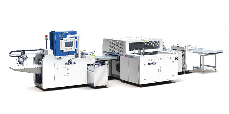
HORDA publishes positioning accuracy of ±0.2 mm for the ZFM-700K. This is a specification for that machine configuration, not a universal tolerance for servo positioning. Confirm the measurement stage and acceptance conditions when testing your own products.