
Standard Rigid Box Machine vs. CCD Rigid Box Production Line
The main difference between photoelectric positioning and CCD vision positioning is how they detect a reference. Photoelectric sensors detect changes in light at a sensing point, while CCD vision systems capture images and locate configured visual features. Neither method alone determines finished-case accuracy: material feeding, motion correction, gluing and folding also affect the result.
Compare Two Things Separately
Positioning technology determines how the machine finds its reference. Production-line configuration determines which operations it completes. A CCD system does not automatically mean inner lining or final box assembly is included.
What Is CCD Positioning in Rigid Box Making?
CCD positioning uses a camera and image-processing software to locate a reference and provide positioning information to the machine controller. The reference may be an edge, registration mark or recognizable pattern, depending on the installed system.
The camera captures an image, the software identifies the configured feature, and the controller calculates the required movement. The positioning mechanism then places or adjusts the material.
“CCD” describes the camera sensor technology. The features a machine can recognize and the corrections it can make depend on its optics, lighting, software and motion system.
How Does Photoelectric Positioning Work?
Photoelectric positioning detects a target through a change in received light, then uses that signal to coordinate material movement. Depending on the sensor, detection may involve a blocked beam, reflected light or a suitable contrast mark.
In a case-making machine, a sensor can indicate when a sheet or board reaches a reference point. The controller coordinates the conveyor or positioning mechanism from that information.
Photoelectric detection does not necessarily mean simple or manual positioning. It can work with servo correction, mechanical guides and multiple detection points to support repeatable placement.
CCD vs. Photoelectric Positioning: What Is the Difference?
Photoelectric systems detect defined optical changes; vision systems analyze an image to locate configured features. Both need a suitable reference and a stable mechanism to turn detection into accurate placement.
Photoelectric Positioning
- Detects a target at a sensing point or within a defined sensing area.
- Can detect presence, edges or suitable marks, depending on sensor type.
- Requires correct sensitivity, mounting and reference selection.
- Works with the machine’s control and motion mechanisms.
CCD Vision Positioning
- Captures an image within the camera’s field of view.
- Locates edges, marks or patterns supported by its software.
- Requires suitable lighting, focus, calibration and feature settings.
- Can provide position and, where supported, angle information for correction.
Neither description establishes which machine will produce better cases. A well-matched photoelectric system may meet the job requirements, while vision guidance may be useful when the required reference is more complex.
When Is CCD Vision Positioning Useful?
CCD vision positioning is useful when the machine needs image-based information to locate the required placement reference. Its value depends on what the installed system can actually recognize.
- Artwork-related placement: Board placement must relate to a printed feature rather than only the sheet edge.
- Position or angle variation: The system must detect displacement and provide information for supported corrections.
- Distinctive reference features: A recognizable shape or pattern provides a useful alignment target.
Reflective foil, low-contrast printing and changing surface finishes can make image recognition more demanding. Test those materials with the proposed lighting and camera setup.
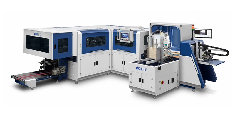
Within HORDA’s rigid box making machine range, positioning technology is one selection factor alongside size limits, board layouts, folding capability and process coverage.
Does CCD Positioning Improve Printed Pattern Alignment?
It can help when the vision system reads the relevant printed feature and the machine uses that information to correct placement. A camera that references only the sheet edge does not automatically align the board to the artwork.
For example, a printed border may need to remain evenly spaced around a finished cover. If the artwork shifts relative to the cut sheet edge, aligning only to that edge may leave the border uneven.
A compatible vision system can use a printed reference instead, but its correction range and supported axes must suit the job. It cannot repair distorted printing or make every part of stretched paper align simultaneously.
Ask during the demonstration: Which feature does the camera read, what movement does it correct, and how is alignment measured after folding?
How Should Positioning Accuracy Be Compared Between Machines?
Compare accuracy at the same processing stage, using the same reference, materials, speed and measurement method. Published figures are difficult to compare when their test conditions differ.
- Separate detection from placement. Sensor repeatability or camera measurement performance describes detection. It does not, by itself, state how accurately the machine places greyboard.
- Check the correction mechanism. Servo movement, gripping, conveyor stability and material slip influence whether the detected offset is corrected successfully.
- Measure the finished result. Inspect board spacing, paper margins, print alignment and folded edges after the relevant operations.
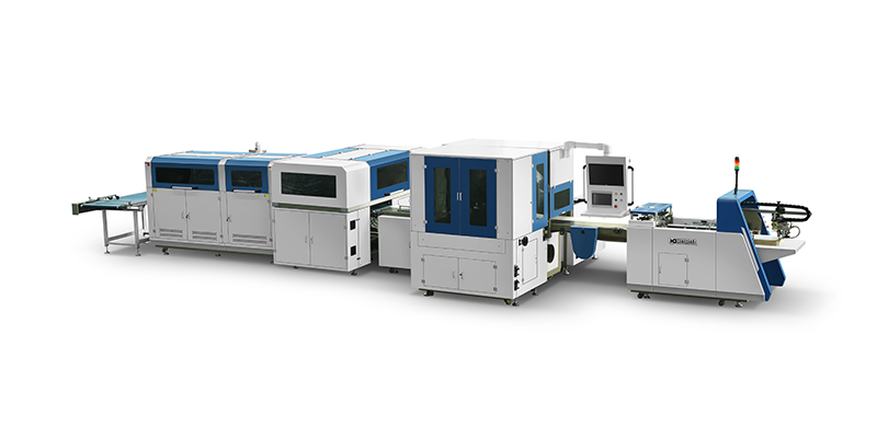
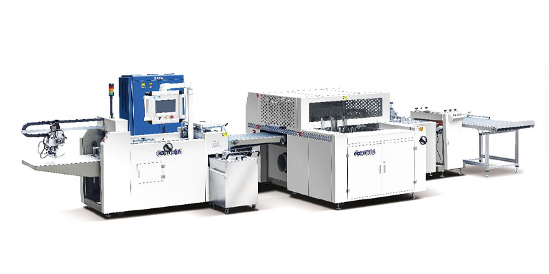
HORDA publishes positioning accuracy of ±0.15 mm for the QZFM-700B CCD production line and ±0.2 mm for the ZFM-700H/1000H extended-format machines. These are model-specific specifications, not universal accuracy ratings for CCD and photoelectric technology.
For a meaningful trial, agree on measurement points and sample quantity. Record variation across a continuous run, together with rejects, stoppages and manual adjustments.
Does a CCD Production Line Include More Processes?
Only when its specified configuration includes them. CCD describes the positioning approach, while an integrated line connects production operations.
For example, HORDA’s QZFM-700B combines case making and inner lining. The ZFM-700H/1000H description covers feeding, gluing, positioning and edge folding. Their process scopes differ as well as their positioning arrangements.
When comparing a standalone case maker with an integrated line, identify the output of each: a wrapped case or an inner-lined case. Magnet installation, tray attachment and complete box assembly require separate confirmation.
Which Positioning System Should You Choose?
Choose the system that can detect your required reference and consistently deliver acceptable cases at your production rate. Base the decision on actual products and demonstrated results.
- Define the reference: Sheet edge, board edge, printed mark or artwork feature.
- Define the tolerance: State where alignment is measured and what variation is acceptable.
- Test difficult materials: Include glossy, dark, reflective or low-contrast covers where relevant.
- Verify correction: Confirm which position and angle deviations the machine can handle.
- Check full-run performance: Compare accepted output, setup effort and operator intervention.
If photoelectric positioning meets the required tolerance and output, it may be a suitable choice. If the job needs image-based reference recognition, evaluate a compatible vision configuration and verify its benefit through the same production test.